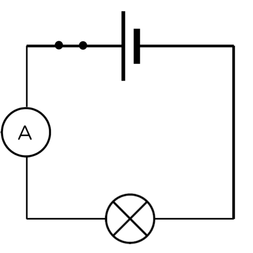
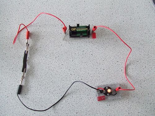
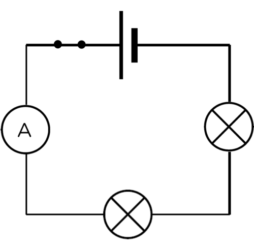
Construct the circuit with the cell, the ammeter, 1 bulb and the switch in series.
|
Previous
Chapter 10: Energy transfer in electrical systems
|
Next
Chapter 12: Visible light
|
Chapter overview
2 weeks
This chapter builds on the Gr 6 and 7 electric circuits work, and the previous chapter of this book. Up until now, we have only been looking at simple circuits. We will now examine the concept of series and parallel circuits. We will look at the difference between these two set-ups in circuits, specifically looking at the effects of adding resistors in series or in parallel and observing the change in brightness of bulbs. The use of ammeters has also been included in this chapter. However, if you do not have these instruments, you can simply do a qualitative study, using the brightness of the bulbs.
You can also use the PhET simulations where learners can build their own circuits and test them out, observing the effects when they add or remove various components. These simulations will run directly within your browser from our website, www.curious.org.za. Here is a link to a guide (in pdf format) written by PhET in the use of some of the electric circuit simulations: phet.colorado.edu/files/teachers-guide/circuit-construction-kit-dc-guide.pdf
3.1 Series circuits (2.5 hours)
|
Tasks |
Skills |
Recommendation |
|
Investigation: What happens when we add more resistors in series? |
Investigating, hypothesising, following instructions, observing, interpreting, recording, analysing, writing, working in groups |
CAPS suggested |
|
Investigation: How does adding more cells in series affect the current? |
Investigating, hypothesising, following instructions, observing, interpreting, recording, analysing, writing, working in groups |
Suggested |
|
Investigation: Testing the current strength |
Investigating, hypothesising, following instructions, observing, interpreting, recording, analysing, writing, working in groups |
Suggested |
3.2 Parallel circuits (3 hours)
|
Tasks |
Skills |
Recommendation |
|
Activity: Series or parallel? |
Identifying, describing |
Suggested |
|
Investigation: How does adding resistors in parallel affect the current strength? |
Investigating, hypothesising, following instructions, observing, interpreting, recording, analysing, writing, working in groups |
CAPS suggested |
|
Investigation: What happens to the current strength when cells are connected in parallel? |
Investigating, hypothesising, following instructions, observing, interpreting, recording, analysing, writing, working in groups |
Suggested |
|
Investigation: Testing the current strength |
Investigating, following instructions, observing, interpreting, recording, analysing, writing, working in groups |
Suggested |
|
Activity: Which metals offer the most resistance? |
Following instructions, observing, interpreting, working in groups |
CAPS suggested |
3.3 Other output devices (0.5 hours)
|
Tasks |
Skills |
Recommendation |
|
Activity: Sankey diagrams |
Drawing, explaining |
Suggested |
|
Activity: History of electricity production |
Research, summarising, working in groups, writing |
CAPS suggested (can be done as homework task) |
|
Activity: Careers |
Research, writing |
Optional |
In the last chapter, and in Gr 6 and 7, we have been looking at electric circuits. These have mostly been series circuits. What does this mean? And how else can a circuit be arranged?
A series circuit is one in which there is only one pathway for the electric current to follow. The components are arranged one after another in a single pathway. When we connect the components we say that they are connected in series. We have already seen examples of series circuits in the last chapter.
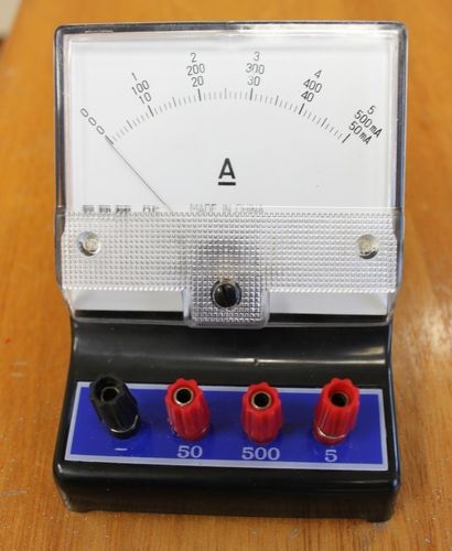
An ammeter is a measuring device used to measure the electric current in the circuit. It is connected into the circuit in series. The current is measured in amperes (A).
The ampere is named after André-Marie Ampère (1775-1836), a French mathematician and physicist. He is considered the father of electrodynamics, which is the study of the effect of electromagnetic forces between electric charges and currents.
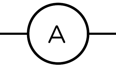
What is the symbol for an ammeter? Draw it here.
Do you think that an ammeter would have a high resistance or a low resistance to the current? Explain your choice.
Ammeters have an extremely low resistance because they must not alter the current they are measuring in any way.
The ampere is often shortened to 'amp'.
A series circuit only provides one pathway for the electrons to follow. Let's investigate what happens when we increase the resistance in a series circuit.
The aim of this investigation is to show the learners that adding more resistors in series causes the overall resistance of the circuit to increase and that this reduces the current strength.
AIM: To investigate the effect of adding resistors to a series circuit.
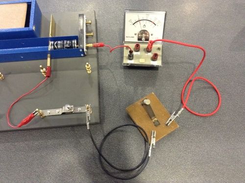
This is a good opportunity for group work if you have enough equipment, but make sure that each learner is able to connect an ammeter correctly and is able to read the ammeter scale accurately. If you do not have sufficient equipment for all the learners, you can do this experiment as a demonstration. Perhaps give several learners an opportunity to come up to the front and help to connect the ammeters. If you do not have any ammeters then you can use the brightness of the bulbs to indicate current strength. The larger the current, the brighter the bulb will glow. This means that if the bulb glows brightly, it must have a large current moving through it. If the bulb is dimmer, it means that there is a smaller current flowing through it.
If you do not have the physical apparatus for this investigation but you do have internet access, use the PhET simulations found here: http://phet.colorado.edu/en/simulation/circuit-construction-kit-dc
The simulations are also useful because the ammeters (and voltmeters) commonly used in school laboratories are often not calibrated correctly or not serviced regularly and so often give slightly inaccurate results.
HYPOTHESIS: Write a hypothesis for this investigation.
This is a learner-dependent answer. The hypothesis should relate the dependent and independent variables and make a prediction. The dependent variable will change as the independent variable is changed. Here is an example of a possible answer:
As the number of resistors increases, the current strength decreases.
MATERIALS AND APPARATUS:
It is important that the torch bulbs have the same resistance and are not randomly selected. The switch is not an essential part of this investigation. It can be left out of the circuit.
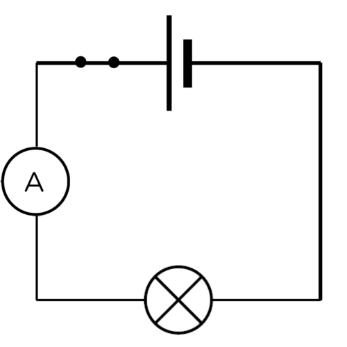
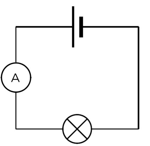
METHOD:
Construct the circuit with the cell, the ammeter, 1 bulb and the switch in series.
Note how brightly the bulb is shining and write down the ammeter reading. Draw a circuit diagram.

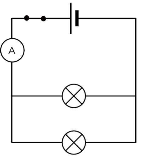
Note how brightly the bulbs are shining and write down the ammeter reading. Draw a circuit diagram.

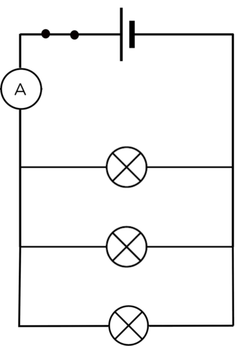
Note how brightly the bulbs are shining and write down the ammeter reading. Draw a circuit diagram for the last circuit you built.
RESULTS:
Complete the table:
|
Number of bulbs in series |
Brightness of bulbs |
Reading on ammeter (A) |
|
1 |
||
|
2 |
||
|
3 |
The brightness of the bulbs is a qualitative comparison. Learners should use "bright, brighter, brightest" as a way to describe the glowing bulbs. The graph should show the quantitative data of the ammeter reading and the number of bulbs. If you do not have an ammeter to take readings, either do not draw a graph, or change the graph to a bar graph which has bright, brighter, brightest as the values on the y-axis. This is not a particularly useful graph but will give the learners a chance to practice drawing a bar graph and give them a visual representation of the decrease in current strength as the number of bulbs increases.
Draw a graph to show the relationship between the number of bulbs and the current.
These results are an example of possible results. The actual results obtained by the learners will differ but the trend should be similar. As the number of bulbs in series increases, both the ammeter reading and bulb brightness should decrease.
|
Number of bulbs in series |
Brightness of bulbs |
Reading on ammeter (A) |
|
1 |
brightest |
0,15 |
|
2 |
bright |
0,07 |
|
3 |
dimmest |
0,05 |
Using standard ammeters may not give perfect results and if the bulbs are allowed to heat up too much in between adding more bulbs, their resistance will be higher. It is important that the learners see a downward trend.
ANALYSIS:
What happened to the brightness of the bulbs as the number of bulbs increased?
The bulbs got dimmer as more bulbs were added.
When you had two bulbs, did they glow with the same brightness, or was one brighter than the other?
The bulbs glowed with the same brightness.
When you had three bulbs, did they glow the same as each other or was one brighter than the others?
The bulbs glowed with the same brightness.
What do your answers to the previous questions tell you about the current in the series circuit?
If all the bulbs glow the same, it means that they all experience the same current. This means that the current is the same everywhere in a series circuit.
What happened to the reading on the ammeter as you added more bulbs in series?
The ammeter reading decreased.
CONCLUSION:
Based on your answers, what happened to the current when more bulbs were added in series?
As more bulbs were added, the current decreased.
Is your hypothesis accepted or rejected?
This answer will depend on the hypothesis written by the learner at the start of the investigation.
As more resistors are added in series, the total resistance of the circuit increases. As the total resistance increases, the current strength decreases. What would happen if we increased the number of cells connected in series? Would the current become larger or smaller? Let's investigate.
This investigation will show that adding more cells in series increases the current strength. Be careful with this activity because if you do not have enough resistance in your circuit, you can damage the torch light bulbs. Use at least two torch light bulbs or a torch light bulb and a resistor in order to keep the resistance high enough. If you have ammeters, you can use quantitative data to show that adding more cells in series increases the current strength. If you do not have ammeters, then use the brightness of the bulbs as qualitative data. Use terms such as dim, bright, brightest. The learners will not be able to draw effective graphs with the qualitative data but you could give them the example data in the teacher's guide and ask them to draw a line graph if they need practice.
AIM: To investigate the effect of increasing the number of cells connected in series on the electric current strength.
HYPOTHESIS: Write a hypothesis for this investigation. Remember to mention how the increase in the number of cells will affect the current strength.
This answer is learner-dependant. They must mention how the dependent variable will be affected by the independent variable. Remember that the hypothesis does not need to be factually correct. They will prove or disprove it by completing the investigation. Here is an example of a possible hypothesis: As the number of cells connected in series increases, the current strength increases.
MATERIALS AND APPARATUS
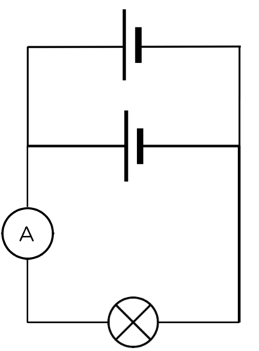
METHOD:
Observe the brightness of the bulbs and record the ammeter reading in the table of results. Draw a circuit diagram.
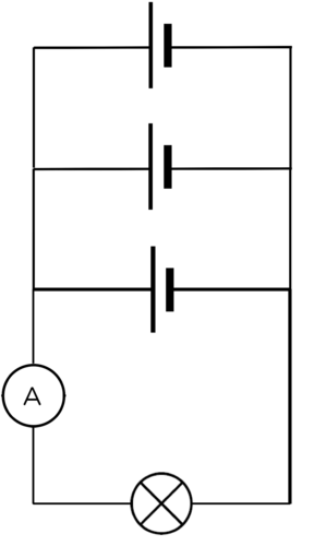
Record the ammeter reading in the table of results. Draw a circuit diagram.

Record the ammeter reading in the table of results. Draw a circuit diagram.
RESULTS:
Complete the table:
|
Number of cells in series |
Brightness of bulbs |
Reading on a mmeter (A) |
|
1 |
||
|
2 |
||
|
3 |
These results are example results. The actual results obtained by the learners will differ but the trend should be similar. As the number of cells increases, both the ammeter reading and the bulb brightness should increase.
|
Number of cells in series |
Brightness of bulbs |
Reading on ammeter (A) |
|
1 |
dimmest |
0.07 |
|
2 |
bright |
0.15 |
|
3 |
brightest |
0.22 |
CONCLUSION:
As the number of cells connected in series increases, so does the current strength.
This answer depends on the learner's original hypothesis.
We have seen that increasing the number of cells in series increases the current, but increasing the number of resistors decreases the current.
We will now investigate the current strength at different points in a series circuit.
The first investigation looked at the decrease in current strength when more resistors were connected in series. This investigation confirms that the current strength is the same at all points in a series circuit. This is an optional investigation. This can be a demonstration if your equipment is limited. This is a good opportunity for group work, but make sure that each learner is able to connect an ammeter correctly and understands the ammeter scale.
INVESTIGATIVE QUESTION:Is the current strength the same at all points in a series circuit?
HYPOTHESIS: Write a hypothesis for this investigation. What do you think will happen in this investigation?
This is a learner-dependant answer. Learners need to mention the independent and dependent variables. The dependent variable will change as the independent variable is changed.
Here are two examples of an acceptable hypothesis:
MATERIALS AND APPARATUS:
METHOD:
Measure the current strength using the ammeter. Draw a circuit diagram of this set up.
Measure the current strength using the ammeter. Draw a circuit diagram of this set up.
Measure the current strength using the ammeter. Draw a circuit diagram of this set up.
RESULTS:
Complete the following table:
|
Position of ammeter in circuit |
Ammeter reading (A) |
|
Between positive terminal of cell and first bulb |
|
|
Between two bulbs |
|
|
Between negative terminal of cell and last bulb |
The ammeter readings should be the same at any point in the series circuit.
CONCLUSIONS:
Write a conclusion based on your results.
The current strength is the same at any point in a series circuit.
Is your hypothesis true or false?
This answer will depend on the hypothesis written by the learner at the start of the investigation.
In a series circuit, there is only one pathway for the electrons to move through. The current strength is the same everywhere in that pathway.
What have we learned about series circuits?
There is only one pathway for the electrons to follow.
The current flows at thesamestrengtheverywhere in a series circuit, because there is only one pathway. We say that the current is the same at all points in the circuit.
If you add more resistors in series, the current in the whole circuit decreases.
Why does the current stay the same at all points? Let's think about how electric current moves through a circuit. Do you remember that we spoke about the delocalised electrons in metals in the last chapter?
Animation showing the movement of electrons. http://www.schoolphysics.co.uk/animations/Electric_current/index.html
The electrons in a conductor normally drift in various different directions within a metal, as shown in the diagram.
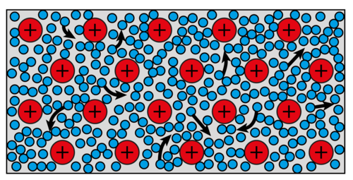
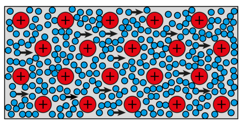
When we build a closed circuit with a cell as an energy source, the electrons will all begin to move towards the positive side of the cell. The rate at which the electrons move, is determined by the resistance of the conductor.
There are electrons everywhere in the conducting wires and electrical components. When the circuit is closed, all the electrons start moving in the same general direction at the same time. This is why a light bulb turns on immediately when you close the switch.
Flip the switch and watch the electrons with this simulation.[link] http://phet.colorado.edu/en/simulation/signal-circuit
The simulation identified in the visit box helps to demonstrate how a light bulb turns on immediately when the switch is turned on.
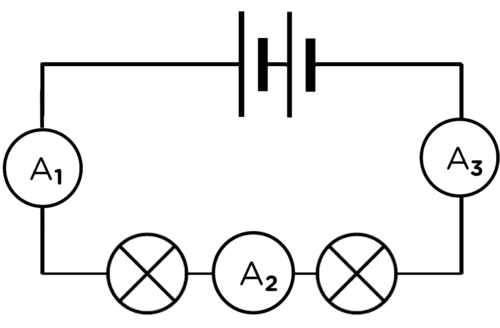
In a series circuit, all the electrons travel through every component and wire as they travel through the circuit. All the electrons experience the same resistance and so they all move at the same rate.
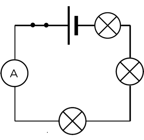
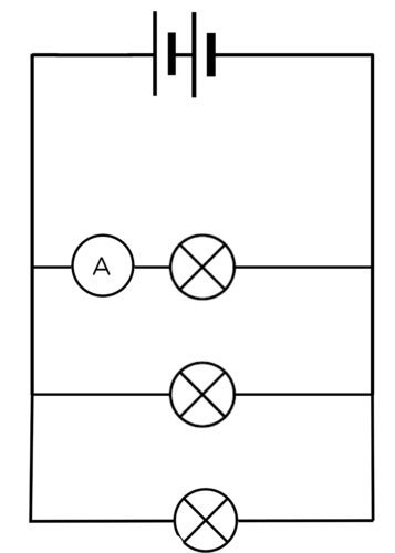
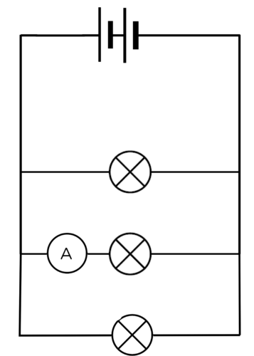
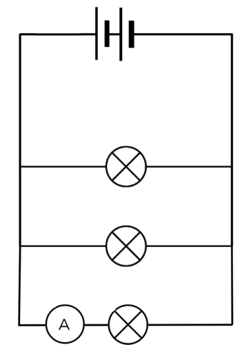
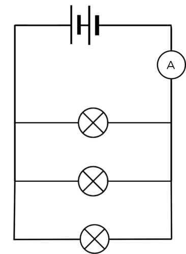
This means that in the diagram below, the readings on all three ammeters will be the same, so: A1= A2= A3
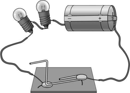
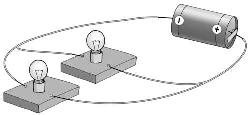
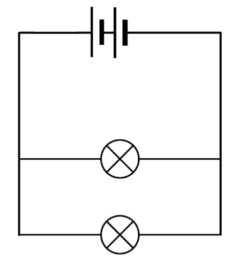
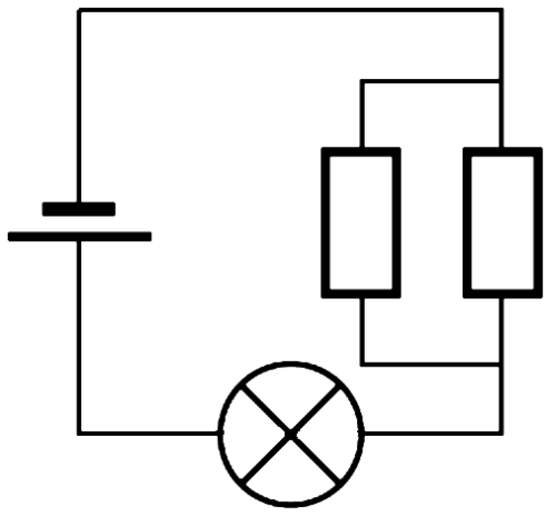
Parallel circuits offer more than one pathway for the electrons to follow. When constructing a parallel circuit, we say that components are connected in parallel.
Look at the diagram which shows how two light bulbs are connected in parallel.
How can you tell whether or not a circuit is connected in series or in parallel? Let's look at some circuit diagrams to tell the difference.
Watch a video that explains the difference between series and parallel circuits
INSTRUCTIONS:
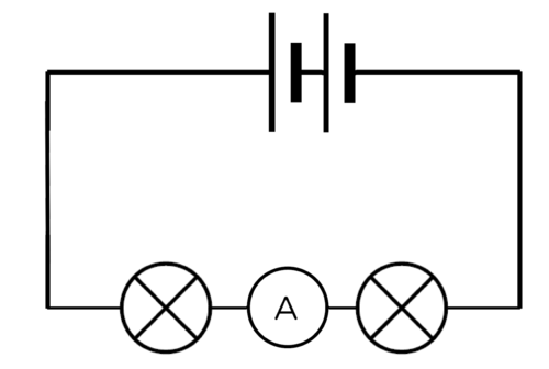
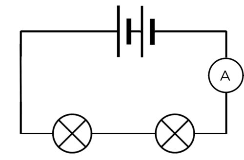
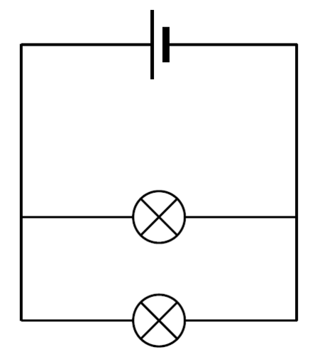
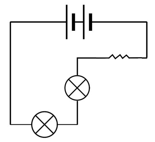
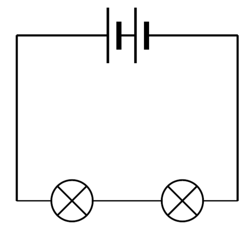
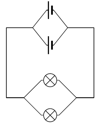
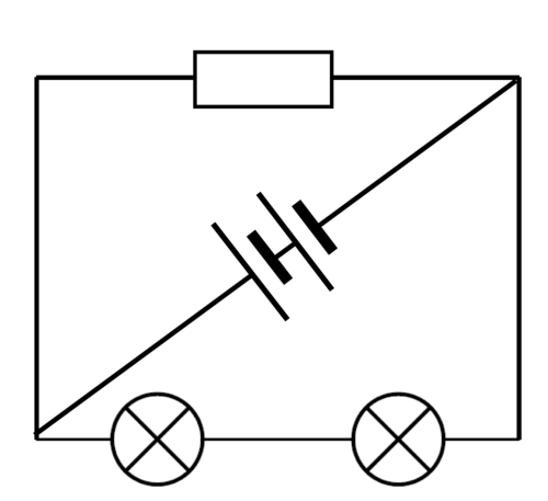
Look at the following circuits and decide which are in series and which are in parallel. The series circuits will only offer one pathway, but the parallel circuits will have more than one pathway for the electrons to follow.
 |
 |
 |
 |
 |
 |
|
series |
parallel |
 |
 |
|
parallel |
series |
Let's investigate how parallel circuits work.
This investigation will show the learners that increasing the number of resistors in parallel to each other, causes the overall resistance of the circuit to decrease and the current strength to increase. There is no need to discuss how to calculate the effective resistance of a parallel circuit. The learners just need a qualitative understanding.
AIM: To investigate the effect of adding resistors in parallel on the current strength.
If you do not have physical apparatus for this investigation but you do have internet access, use the PhET simulations found here: http://phet.colorado.edu/en/simulation/circuit-construction-kit-dc
HYPOTHESIS: Write a hypothesis for this investigation.
This is a learner dependant answer. Learners need to mention the independent and dependent variables. The dependent variable will change as the independent variable is changed.
Here are two examples of an acceptable hypothesis:
MATERIALS AND APPARATUS:
It is important that the torch bulbs are the same resistance and not randomly selected. The switch and ammeter are not strictly necessary for this experiment. They can be left out if you don't have enough switches or ammeters.
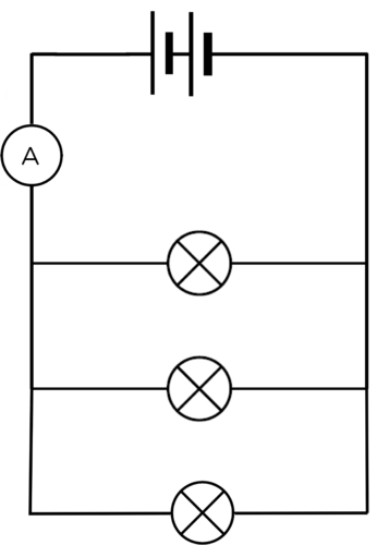
METHOD:
Note how brightly the bulb is shining and record the ammeter reading. Draw a diagram of your circuit.
RESULTS:
Complete the table:
The brightness of the bulbs is a qualitative description. The learners should use "bright, brighter, brightest" in order to describe the glowing bulbs.
|
Number of bulbs in parallel |
Brightness of bulbs |
Reading on ammeter (A) |
|
1 |
||
|
2 |
||
|
3 |
Draw a graph to show the relationship between the number of bulbs and the current.
The graph will show the relationship between the main current (reading on the ammeter) and the number of bulbs connected in parallel. As more bulbs are connected in parallel, the current strength should increase because the overall resistance of the circuit decreases. This means that the graph should be a straight line with an increasing trend. Standard ammeters may not be accurate enough to produce a perfectly straight line. This is not as important as seeing the upward trend.
These results are just an example. The actual results will depend on the circuit set up by the learner.
|
Number of bulbs in parallel |
Brightness of bulbs |
Reading on ammeter (A) |
|
1 |
dimmest |
0.15 |
|
2 |
brighter |
0.3 |
|
3 |
brightest |
0.45 |
ANALYSIS:
What happened to the brightness of the bulbs as the number of bulbs increased?
The bulbs got brighter as more bulbs were added.
When you had two bulbs, did they glow with the same brightness or was one brighter than the other?
The bulbs glowed with the same brightness.
When you had three bulbs, did they glow the same brightness or was one brighter than the others?
The bulbs glowed with the same brightness.
What do your answers to the previous questions tell you about the current in the parallel branches of the circuit?
As all the bulbs are identical, if they all glow the same brightness, then they all experience the same current. This means that the current is the same in each branch.
What happened to the reading on the ammeter as you added more bulbs in parallel?
The ammeter reading increased.
CONCLUSION:
Based on your answers, what happened to the current when more bulbs were added in parallel?
As more bulbs were added, the current increased.
Is your hypothesis true or false?
This answer will depend on the hypothesis written by the learner at the start of the investigation.
As more resistors are added in parallel, the total current strength increases. The overall resistance of the circuit must therefore have decreased. The current in each light bulb was the same because all the bulbs glowed with the same brightness. This tells us that the current of electrons must have split up and moved through each of the branches.
We can also connect cells in parallel. What would happen if we increased the number of cells connected in parallel? Would the current get stronger or weaker?
AIM: To investigate how increasing the number of cells connected in parallel affects the current strength in a circuit.
HYPOTHESIS: Write a hypothesis for this investigation.
This is a learner-dependent answer. Learners need to identify the independent and dependent variables. The dependent variable will change as the independent variable is changed.
Here are two examples of an acceptable hypothesis:
MATERIALS AND APPARATUS
The ammeter is not essential to the experiment. The brightness of the bulb can serve as a qualitative measure.
METHOD:
Set up a circuit which has one cell, the ammeter and the torch light bulb in series with each other. Draw a circuit diagram of your circuit.
Connect another cell in parallel with the first cell. To connect the second cell in parallel, connect a wire from the positive terminal of the first cell to the positive terminal of the second cell. Connect another wire between the negative terminal of the first battery and the negative terminal of the second battery. Draw a circuit diagram of your circuit.
Connect a third cell in parallel to the other two cells. Draw a circuit diagram of your circuit.
RESULTS:
Complete the table:
The brightness of the bulbs is a qualitative description. The learners should use "bright, brighter, brightest" in order to describe the glowing bulbs. The ammeter readings should stay the same.
|
Number of cells in parallel |
Brightness of bulb |
Reading on ammeter (A) |
|
1 |
||
|
2 |
||
|
3 |
CONCLUSION:
What did you notice about the brightness of the bulbs?
The brightness of the bulbs should not change.
What did you notice about the ammeter readings?
The ammeter readings are the same.
What conclusion can you draw from your results?
Adding cells in parallel does not change the overall current strength.
Adding cells in parallel has no overall effect on the current strength. The current strength stays the same if you add cells in parallel.
We saw that the current strength increased when bulbs were connected in parallel. However, we were only testing the current strength at one point in the parallel circuit. How does the current compare in the different pathways of the circuit? Let's do an investigation to find out.
The first investigation looked at the increase in current strength when more resistors were connected in parallel. This investigation confirms that the current strength is not the same at all points in a parallel circuit. This is a good opportunity for group work, but make sure that each learner is able to connect and read an ammeter correctly. If you do not have enough equipment to allow for small groups to build the circuits, you can rather use this investigation as a demonstration. Perhaps give several learners an opportunity to come up to the front and help to connect the ammeters.
INVESTIGATIVE QUESTION: Is the current strength equal at all points in a parallel circuit?
MATERIALS AND APPARATUS:
METHOD:
RESULTS:
|
Position of ammeter in circuit |
Ammeter reading (A) |
|
between the cell and first pathway |
|
|
in the first pathway |
|
|
in the second pathway |
|
|
in the third pathway |
|
|
between the cell and the first pathway |
These are some example readings to show the trend:
|
Position of ammeter in circuit |
Ammeter reading (A) |
|
between cell and first pathway |
0.9 |
|
in the first pathway |
0.3 |
|
in the second pathway |
0.3 |
|
in the third pathway |
0.3 |
|
between the cell and the first pathway |
0.9 |
If you do not use identical bulbs, then the readings in each of the branches will not be identical, but they will add up to reading in the main branch. If possible, it is worthwhile to demonstrate this to learners.
CONCLUSION:
Write a conclusion based on your results.
The current strength is not the same at all points in a parallel circuit. If the bulbs are identical, then the current is the same in the three branches, however the current in the main part of the circuit is greater than that in the individual pathways. The current in the main part of the circuit is the sum of the currents in the pathways.
Is your hypothesis true or false?
This answer will depend on the hypothesis written by the learner at the start of the investigation.
What have we learned about parallel circuits?
There is more than one pathway for the current to follow.
If you add more resistors in parallel, the total current supplied by the cell in the circuit increases.
Why does the current divide when offered an alternative pathway?
Imagine that you are sitting in a school hall during assembly. You are bored and waiting for it to end so that you can go out to break to chat to your friends. There is only one exit from the hall. When you are dismissed, everyone has to exit through the same door. It takes a while because only some learners can leave at a time.
Now imagine that there is a second door that is the same as the first door. Now you and your friends have a choice of which door to go through. The speed at which the learners exit the hall will increase and some of you will exit through the first door while others will exit through the second door. No one can go through both doors at the same time.
This is similar to the way current behaves when in a parallel circuit. As the electrons approach the branch in the circuit, some electrons will take the first path and others will take the other path. The current is divided between the two pathways.
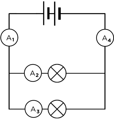
In the following circuit A1 = A4 and A1 = A2 + A3 and A4 = A2 + A3
We have looked at how resistors and cells behave in series and parallel circuits. Let's look at how different metals conduct electricity. All conductors have some resistance in a circuit. Are some metals better conductors of electricity than others?
Let's have a look at which metals offer more resistance than others to the flow of charge (current) through an electric circuit .
This activity only compares the effect of the type of material on resistance. The other factors that affect resistance will be covered in the Grade 9 Energy and Change syllabus.
Each metal will have a particular resistance based on the resistivity. You do not need to measure the resistance of each metal, all that is required is a qualitative description of the light bulb. The brighter the light bulb, the higher the current. If there is a high current it means that there is little resistance. So the brighter the bulb glows, the less resistance offered by the metal wire. The learners may make small mistakes if the brightness of the bulbs is difficult to distinguish.
Use whichever metal wires you have available. Try to get copper and nickel. You could twist aluminium foil into a wire (just make sure it is the same length and approximate thickness as the other metals). Aluminium wire will often ignite if placed in a circuit so test it beforehand and make sure that it does not get too hot. If you use the materials listed below, then nichrome will have the highest resistance, followed by zinc, then aluminium and copper has the lowest resistance of the four.
MATERIALS:
The actual length of wire that you use is not important, but they should all be the same length and thickness. If you cannot find these metals, any other combination of metals can be successfully used.
INSTRUCTIONS
Observe the brightness of the bulb.
QUESTIONS:
Draw a circuit diagram of your apparatus.
An example circuit diagram with the break in the circuit where metals are to be tested shown on the left.
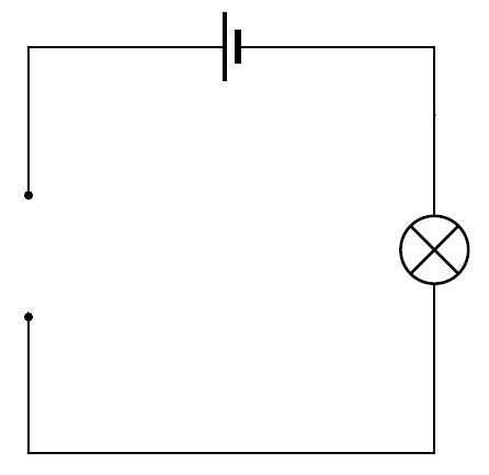
Why can we use the brightness of the bulb to qualitatively measure resistance?
High resistance opposes the movement of electrons, decreasing the current so there is less energy for the light bulb. The higher resistance wire will cause the bulb to be dimmer than the lower resistance wire.
List the metals in order of increasing resistance.
Copper, aluminium, zinc and nichrome.
Why do you think copper is used for connecting wires in electrical circuits?
Copper has an extremely low resistance, and so has a minimal effect on the overall resistance of the circuit. Other materials would add to the overall resistance of the circuit, decreasing the maximum possible current in that circuit.
There are several factors which influence the amount of resistance a material offers to an electric current. We have seen that the type of material is one of those factors.
In Gr 9 we will look at the other factors that influence resistance. If you want to see the content in other grades, remember that you can visit www.curious.org.za
Light bulbs are not the only devices used in electrical circuits. Devices that use electrical energy to function, including light bulbs, are called output devices. Let's look at some other common examples of output devices.
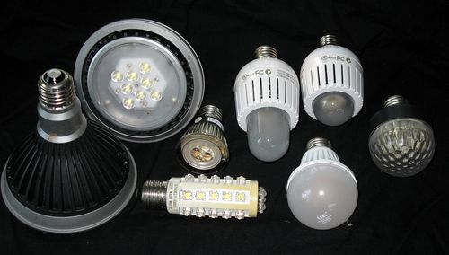
LEDs are widely used electronic devices. They are small lights but they do not have a filament like an incandescent bulb has. They therefore cannot burn out, as there is no filament to wear out, and they do not get as hot. LEDs are used in electronic timepieces, high definition televisions and many other applications. Larger LEDs are also replacing traditional light bulbs in many homes because they do not use as much electricity. They last longer than incandescent bulbs and are more efficient.
Watch this video about the history of the LED
In the last chapter, we looked at the energy transfers in an electrical system. We will now represent energy transfer within electrical systems in a different way. We will apply this new representation to the difference between energy outputs in an LED and an incandescent light bulb.
Video on drawing a basic Sankey diagram.
Sankey diagrams were first introduced in the Gr 7 CAPS workbook as a way of representing the transfers of energy within a system, specifically focusing on the transfer of input energy to useful and wasted output energy. They provide a very clear illustration of the process. This links back to the previous chapter to reinforce learning.
You might have drawn Sankey diagrams in Grade 7. If not, here is some quick revision.
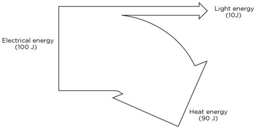
In an energy system, input energy is transferred to useful output energy and wasted output energy. A Sankey diagram is a visual and proportional representation of the energy transfers that happen in a system.
For example, a kettle uses about 2000 J of input energy, but only about 1400 J is used to heat the water. The remaining 600 J is wasted as sound. Here is the Sankey diagram to represent the energy transfer.

Remember that energy is measured in joules (J).
QUESTIONS:
We will now compare an LED with an incandescent light bulb.
Draw a Sankey diagram for an LED if the input energy is 100 J, 75 J of energy is used to produce light and the rest is lost as heat.

Draw a Sankey diagram for a filament light bulb if the input energy is 100 J, the wasted heat energy is 80 J and the rest produces light.
Which bulb do you think is more efficient? Explain your answer.
The LED bulb is more efficient as more of the input energy is transferred to useful output (light) than is wasted as heat. In the filament light bulb, much more energy is wasted as heat.
Can you think of any other output devices? Make a list of as many as you can.
Some are: motors, buzzers, beepers.
INSTRUCTIONS:
The timeline does not need to be too specific. We want learners to realise that this was not an overnight discovery, but involved many people over a significant time. Here are some pertinent facts. This list is not complete and not all of the dates are necessary. Another useful resource is available here: http://www.timetoast.com/timelines/118814
An electricity timeline animation. http://resources.schoolscience.co.uk/britishenergy/14-16/index.htm
INSTRUCTIONS:
Write a short paragraph describing the career. Include information on how one can study or prepare for your chosen career.
The Eskom website has information regarding various careers and the internet has many different sources.
 |
 |
 |
 |
 |
 |
 |
 |
 |
|
Series |
Parallel |
Series |
 |
 |
 |
|
Parallel |
Series |
Parallel |
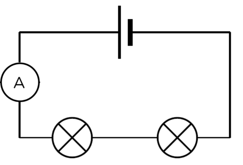
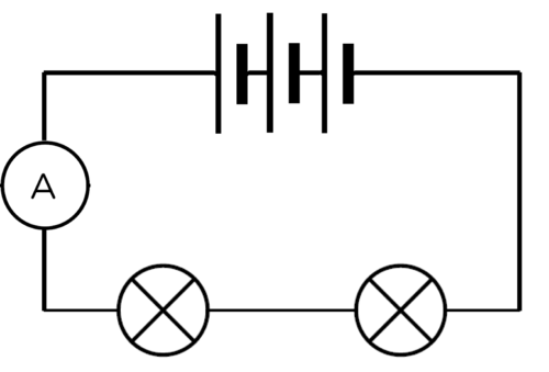
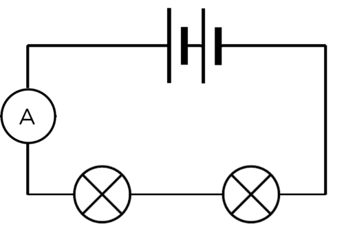
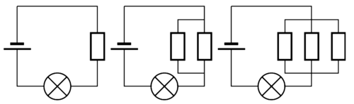
Look at the three circuit diagrams. Rank the circuits from brightest bulb to dimmest bulbs. [3 marks]
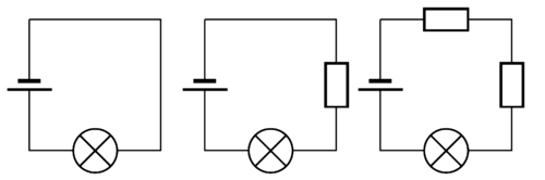
Brightest, bright, dim
Explain your choices in the previous question. [5 marks]
The first circuit has the brightest bulb because it has the least resistance and so it has the highest current. The third circuit has the highest resistance because it has two resistors connected in series with the light bulb. The more resistors connected in series, the higher the resistance and the lower the current.
Look at the three circuit diagrams. Rank the circuits from brightest bulb(s) to dimmest bulb(s). [3 marks]
Dimmest, bright, brightest
Explain your choices in the previous question. [5 marks]
The third circuit will have the brightest bulb because adding resistors in parallel lowers the overall resistance in the circuit. The current is therefore greater and the bulb shines brighter. The first circuit is the dimmest because it has no parallel branches, and so offers the highest resistance.
Look at the circuit diagram below. Each light bulb is identical.
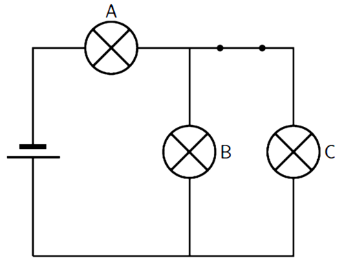
Is this a series or parallel circuit? Explain your answer. [2 mark]
How do the brightness of bulbs A, B and C compare? (which is the brightest?) [3 marks]
What would happen to the brightness of the bulbs if the switch was opened? Explain your answer. [5 marks]
This circuit has both series components (the cell and bulb A are in series) and a parallel branch consisting of bulb B and C.
Bulb A is the brightest, Bulbs B and C would have the same brightness as each other.
If switch S is opened, then bulb C will not glow. Bulbs A and B would now have equal brightness but they would be dimmer than when the switch was closed. A and B would now be in series with each other and there is no parallel branch. The overall resistance of the circuit would therefore be higher, resulting in a smaller current.
Study the following diagram.

What is the relationship between the ammeter readings on A1 and A4? In other words, how do the current strengths compare at these points in the circuit? Explain your answer. [3 marks]
What is the relationship between the ammeter readings on A1, A2 and A3? In other words, how do the current strengths compare at these points in the circuit? Explain your answer. [3 marks]
A1 = A4. The total current flows through the circuit at both of these points.
A1 = A2 + A3. The current splits between parallel branches in a circuit.
Total [38 marks]
|
Previous
Chapter 10: Energy transfer in electrical systems
|
Table of Contents |
Next
Chapter 12: Visible light
|