Describe what is meant by the internal resistance of a real battery.
Real batteries are made from materials which have
resistance. This means that real batteries are not just sources of
potential difference (voltage), but they also possess internal
resistance.
So internal resistance is a measure of the resistance of the material that the battery is made of.
Explain why there is a difference between the emf and terminal voltage of a battery if the load (external
resistance in the circuit) is comparable in size to the battery's internal resistance
The emf of a battery is essentially constant
because it only depends on the chemical reaction (that converts chemical
energy into electrical energy) going on inside the battery. Therefore,
we can see that the voltage across the terminals of the battery is
dependent on the current drawn by the load. The higher the current, the
lower the voltage across the terminals, because the emf is constant. By
the same reasoning, the voltage only equals the emf when the current is
very small.
What is the internal resistance of a battery if its emf is \(\text{6}\) \(\text{V}\) and the potential
difference across its terminals is \(\text{5,8}\) \(\text{V}\) when a current of \(\text{0,5}\) \(\text{A}\)
flows in the circuit when it is connected across a load?
The voltage drop across the internal resistance is the difference between the emf and
the terminal voltage when the battery is connected across a load. The internal resistance
we treat as an ohmic resistor in series with a perfect battery. We know the voltage with
and without a load and we know the current so we can use Ohm's law to determine the
internal resistance:
\begin{align*}
V_r&= Ir \\
(6)-(5,8)&= (0,5)r \\
r &= \frac{0,2}{0,5} \\
& = \text{0,4}\text{ Ω}
\end{align*}
\(\text{0,4}\) \(\text{Ω}\)
A \(\text{12,0}\) \(\text{V}\) battery has an internal resistance of \(\text{7,0}\) \(\text{Ω}\).
What is the maximum current this battery could supply?
What is the potential difference across its terminals when it is supplying a current of 150.0 mA?
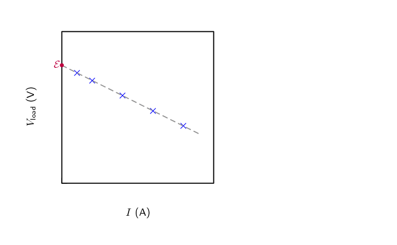
Draw a sketch graph to show how the terminal potential difference varies with the current supplied if
the internal resistance remains constant. How could the internal resistance be obtained from the graph?
What is the maximum current this battery could supply?
What is the potential difference across its terminals when it is supplying a current of 150.0 mA?
\begin{align*}
V & =\mathcal{E} - Ir \\
& =(\text{12,0})- (\text{1,50} \times \text{10}^{-\text{1}})(\text{7,0}) \\
& =\text{10,95} \\
& =\text{10,95}\text{ V}
\end{align*}
Draw a sketch graph to show how the terminal potential difference varies with the current supplied if the
internal resistance remains constant. How could the internal resistance be obtained from the graph?
The slope of the graph is the internal resistance.
In a hearing aid a battery supplies a current of 25.0 mA through a resistance of 400 \(\Omega\). When the
volume is increased, the resistance is changed to 100 \(\Omega\) and the current rises to 60 mA. What is the
emf and internal resistance of the cell?
We have two unknowns but information for two different scenarios so we can solve simultaneously.
The emf is \(\text{10,0}\) \(\text{V}\) and the internal resistance is \(\text{1,1428} \times
\text{10}^{-\text{2}}\) \(\text{Ω}\).
A battery is connected in series with a rheostat and an ammeter. When the resistance of the resistor is 10
\(\Omega\) the current is 2.0 A. When the resistance is 5 \(\Omega\) the current is 3.8 A. Find the emf and
the internal resistance of the battery.
We have two unknowns but information for two different scenarios so we can solve simultaneously.
The emf is \(\text{21,11}\) \(\text{V}\) and the internal resistance is \(\text{0,55}\) \(\text{Ω}\).
When a cell is connected directly across a high resistance voltmeter the reading is
\(\text{1,5}\) \(\text{V}\). When the cell is shorted through a low resistance ammeter the current is
\(\text{2,5}\) \(\text{A}\). What is the emf and internal resistance of the cell?
In the case of the very high resistance voltmeter we need to assume that the current is zero. This means
that
the measurement is actually the emf and the potential difference across the internal resistance obeys Ohm's
law,
\(V=Ir=(0)r=0\).
In the case of a very low resistance ammeter, we can assume that the current that is flowing is the maximum
current possible. We know the emf and the maxmimum curren so we can find \(r\):
The emf is \(\text{1,5}\) \(\text{V}\) and the internal resistance is \(\text{0,6}\) \(\text{Ω}\).
10.4 Evaluating internal resistance in circuits (ESCPW)
Approach (ESCPX)
The approach to solving problems that involve the internal resistance of batteries is straightforward, you just
need to understand that each battery in previous examples was a source of emf, \(\mathcal{E}\), and a small
resistor, \(r\), and then solve as before but include \(r\) in your calculations.
An important thing to realise is that the potential difference you calculated or were given in previous
examples is not the emf, it is the emf less that potential difference across the internal resistance.
To emphasise that internal resistance is an extension to what you have already done we are going to take
previous worked examples and consider the internal resistance of the battery. If the internal resistance did not
behave like an ohmic resistor this wouldn't be possible but we won't deal with cases like that.
Applications (ESCPY)
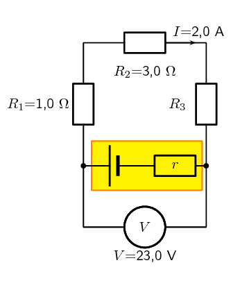
Worked example 7: Internal resistance in circuit with resistors in series
For the following circuit, calculate:
the potential differences \(V_\text{1}\), \(V_\text{2}\) and \(V_\text{3}\) across the resistors
\(R_\text{1}\), \(R_\text{2}\), and \(R_\text{3}\)
.
the resistance of \(R_\text{3}\).
the resistance of \(R_\text{3}\).
If the internal resistance is \(\text{0,1}\) \(\text{Ω}\), what is the emf of the battery and what
power is dissipated by the internal resistance of the battery?
Note
This is a very similar question to what you have seen earlier. This is to highlight the
fact that the approach when dealing with internal resistance is built on all the same
principles you have already been working with.
Determine how to approach the problem
We are given the potential difference across the cell and the current in the circuit, as well as the
resistances of two of the three resistors. We can use Ohm's Law to calculate the potential difference across
the known resistors. Since the resistors are in a series circuit the potential difference is \(V =
V_\text{1} + V_\text{2} + V_\text{3}\) and we can calculate \(V_\text{3}\). Now we can use this information
to find the potential difference across the unknown resistor \(R_\text{3}\).
Calculate potential difference across \(R_\text{1}\)
Using Ohm's Law:
\begin{align*}
R_\text{1} &= \frac{V_\text{1}}{I} \\
I \cdot R_\text{1} &= I \cdot \frac{V_\text{1}}{I} \\
V_\text{1} &= {I}\cdot{R_\text{1}}\\
&= 2 \cdot 1 \\
V_\text{1} &= \text{2}\text{ V}
\end{align*}
Calculate potential difference across \(R_\text{2}\)
Again using Ohm's Law:
\begin{align*}
R_\text{2} &= \frac{V_\text{2}}{I} \\
I \cdot R_\text{2} &= I \cdot \frac{V_\text{2}}{I} \\
V_\text{2} &= {I}\cdot{R_\text{2}}\\
&= 2 \cdot 3 \\
V_\text{2} &= \text{6}\text{ V}
\end{align*}
Calculate potential difference across \(R_\text{3}\)
Since the potential difference across all the resistors combined must be the same as the potential
difference across the cell in a series circuit, we can find \(V_\text{3}\) using:
\begin{align*}
V &= V_\text{1} + V_\text{2} + V_\text{3}\\
V_\text{3} &= V - V_\text{1} - V_\text{2} \\
&= 23 - 2 - 6 \\
V_\text{3}&= \text{15}\text{ V}
\end{align*}
Find the resistance of \(R_\text{3}\)
We know the potential difference across \(R_\text{3}\) and the current through it, so we can use Ohm's Law
to calculate the value for the resistance:
\begin{align*}
R_\text{3} &= \frac{V_\text{3}}{I}\\
&= \frac{\text{15}}{\text{2}} \\
R_\text{3}&= \text{7,5}~\Omega
\end{align*}
Potential difference across the internal resistance of the battery
The value of the emf can be calculated from the potential difference of the load and the potential
difference across the internal resistance.
We know that the power dissipated in a resistor is given by \(P=VI=I^2R=\dfrac{V^2}{R}\) and we know the
current in the circuit, the internal resistance and the potential difference across it so we can use any
form of the equation for power:
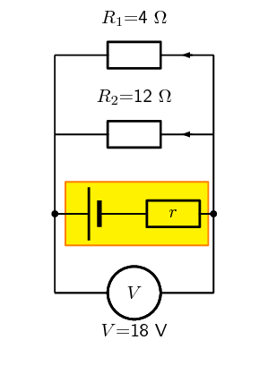
Worked example 8: Internal resistance and resistors in parallel
The potential difference across a battery measures 18 V when it is connected to two parallel resistors of
\(\text{4,00}\) \(\Omega\) and \(\text{12,00}\) \(\Omega\) respectively. Calculate the current through the
cell and through each of the resistors. If the internal resistance of the battery is \(\text{0,375}\)
\(\text{Ω}\) what is the emf of the battery?
First draw the circuit before doing any calculations
Determine how to approach the problem
We need to determine the current through the cell and each of the parallel resistors. We have been given
the potential difference across the cell and the resistances of the resistors, so we can use Ohm's Law to
calculate the current.
Calculate the current through the cell
To calculate the current through the cell we first need to determine the equivalent resistance of the rest
of the circuit. The resistors are in parallel and therefore:
\begin{align*}
\frac{\text{1}}{R} &= \frac{\text{1}}{R_\text{1}} + \frac{\text{1}}{R_\text{2}} \\
&= \frac{\text{1}}{\text{4}} + \frac{\text{1}}{\text{12}} \\
&= \frac{3+1}{\text{12}} \\
&= \frac{\text{4}}{\text{12}} \\
R &= \frac{\text{12}}{\text{4}} = \text{3,00} \ \Omega
\end{align*}
Now using Ohm's Law to find the current through the cell:
\begin{align*}
R &= \frac{V}{I} \\
I &= \frac{V}{R} \\
&= \frac{\text{18}}{\text{3}} \\
I &= \text{6,00}\text{ A}
\end{align*}
Now determine the current through one of the parallel resistors
We know that for a purely parallel resistor configuration, the potential difference across the cell is the
same as the potential difference across each of the parallel resistors. For this circuit:
\begin{align*}
V &= V_\text{1} = V_\text{2} = \text{18}\text{ V}
\end{align*}
Let's start with calculating the current through \(R_\text{1}\) using Ohm's Law:
\begin{align*}
R_\text{1} &= \frac{V_\text{1}}{I_\text{1}} \\
I_\text{1} &= \frac{V_\text{1}}{R_\text{1}} \\
&= \frac{\text{18}}{\text{4}} \\
I_\text{1} &= \text{4,50}\text{ A}
\end{align*}
Calculate the current through the other parallel resistor
We can use Ohm's Law again to find the current in \(R_\text{2}\):
\begin{align*}
R_\text{2} &= \frac{V_\text{2}}{I_\text{2}} \\
I_\text{2} &= \frac{V_\text{2}}{R_\text{2}} \\
&= \frac{\text{18}}{\text{12}} \\
I_\text{2} &= \text{1,50}\text{ A}
\end{align*}
An alternative method of calculating \(I_\text{2}\) would have been to use the fact that the currents
through each of the parallel resistors must add up to the total current through the cell:
\begin{align*}
I &= I_\text{1} + I_\text{2} \\
I_\text{2} &= I - I_\text{1} \\
&= 6 - 4.5 \\
I_\text{2} &= \text{1,5}\text{ A}
\end{align*}
Determine the emf
This total current through the battery is the current through the internal resistance of the battery.
Knowing the current and resistance allows us to use Ohm's law to determine the potential difference across
the internal resistance and therefore the emf of the battery.
Using Ohm's law we can determine the potential difference across the internal resistance:
\begin{align*}
V &=I \cdot r \\
&=\text{6} \cdot \text{0,375} \\
&= \text{2,25}\text{ V}
\end{align*}
We know that the emf of the battery is the potential difference across the terminal summed with the
potential difference across the internal resistance so:
The current through the cell is \(\text{6,00}\) \(\text{A}\).
The current through the \(\text{4,00}\) \(\Omega\) resistor is \(\text{4,50}\) \(\text{A}\).
The current through the \(\text{12,00}\) \(\Omega\) resistor is \(\text{1,50}\) \(\text{A}\).
The emf of the battery is \(\text{20,25}\) \(\text{V}\).
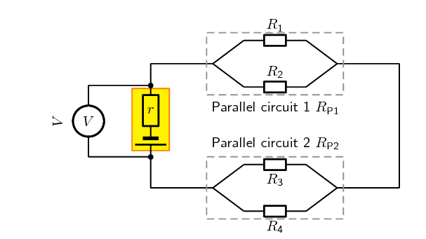
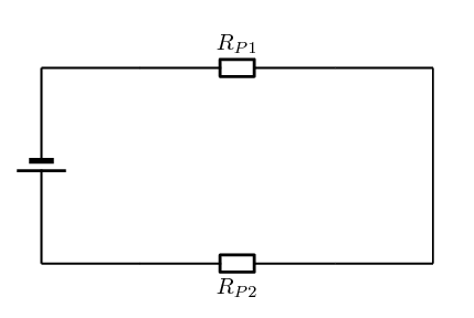
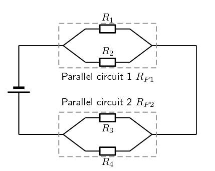
Worked example 9: Power in series and parallel networks of resistors
Given the following circuit:
The current leaving the battery is \(\text{1,07}\) \(\text{A}\), the total power dissipated in the external
circuit is \(\text{6,42}\) \(\text{W}\), the ratio of the total resistances of the two parallel networks
\(R_{P\text{1}} : R_{P\text{2}}\) is 1:2, the ratio \(R_\text{1} : R_\text{2}\) is 3:5 and
\(R_\text{3}=\text{7,00}\text{ Ω}\).
Determine the:
potential difference of the battery,
the power dissipated in \(R_{P\text{1}}\) and \(R_{P\text{2}}\), and
if the battery is labelled as having an emf of \(\text{6,50}\) \(\text{V}\) what is the value of the
resistance of each resistor and the power dissipated in each of them.
What is required
In this question you are given various pieces of information and asked to determine the power dissipated in
each resistor and each combination of resistors. Notice that the information given is mostly for the overall
circuit. This is a clue that you should start with the overall circuit and work downwards to more specific
circuit elements.
Calculating the potential difference of the battery
Firstly we focus on the battery. We are given the power for the overall circuit as well as the current
leaving the battery. We know that the potential difference across the terminals of the battery is the
potential difference across the circuit as a whole.
We can use the relationship \(P=VI\) for the entire circuit because the potential difference is the same as
the potential difference across the terminals of the battery:
\begin{align*}
P &=VI \\
V &= \frac{P}{I} \\
&=\frac{\text{6,42}}{\text{1,07}} \\
&= \text{6,00}\text{ V}
\end{align*}
The potential difference across the battery is \(\text{6,00}\) \(\text{V}\).
Power dissipated in \(R_{P\text{1}}\) and \(R_{P\text{2}}\)
Remember that we are working from the overall circuit details down towards those for individual elements,
this is opposite to how you treated this circuit earlier.
We can treat the parallel networks like the equivalent resistors so the circuit we are currently dealing
with looks like:
We know that the current through the two circuit elements will be the same because it is a series circuit
and that the resistance for the total circuit must be: \(R_{Ext}=R_{P\text{1}}+R_{P\text{2}}\). We can
determine the total resistance from Ohm's Law for the circuit as a whole:
\begin{align*}
V_{battery}&=IR_{Ext} \\
R_{Ext} &=\frac{V_{battery}}{I} \\
&=\frac{\text{6,00}}{\text{1,07}}\\
&=\text{5,61}\text{ Ω}
\end{align*}
We know that the ratio between \(R_{P\text{1}} : R_{P\text{2}}\) is 1:2 which means that we know:
\begin{align*}
R_{P\text{1}} &= \frac{\text{1}}{\text{2}}R_{P\text{2}} \ \ \text{and} \\
R_T &= R_{P\text{1}} + R_{P\text{2}} \\
& = \frac{\text{1}}{\text{2}}R_{P\text{2}} + R_{P\text{2}} \\
&=\frac{\text{3}}{\text{2}}R_{P\text{2}} \\
(\text{5,61}) &=\frac{\text{3}}{\text{2}}R_{P\text{2}} \\
R_{P\text{2}} &= \frac{\text{2}}{\text{3}}(\text{5,61}) \\
R_{P\text{2}} &= \text{3,74}\text{ Ω}
\end{align*}
and therefore:
\begin{align*}
R_{P\text{1}} &= \frac{\text{1}}{\text{2}}R_{P\text{2}} \\
&=\frac{\text{1}}{\text{2}}(3.74) \\
&= \text{1,87}\text{ Ω}
\end{align*}
Now that we know the total resistance of each of the parallel networks we can calculate the power
dissipated in each:
\begin{align*}
P_{P\text{1}} &= I^2R_{P\text{1}} \\
&= (\text{1,07})^2(\text{1,87}) \\
&= \text{2,14}\text{ W}
\end{align*}
and
\begin{align*}
P_{P\text{2}} &= I^2R_{P\text{2}} \\
&= (\text{1,07})^2(\text{3,74}) \\
&= \text{4,28}\text{ W}
\end{align*}
These values will add up to the original power value we had for the external circuit. If they didn't
we would have made a calculation error.
Parallel network 1 calculations
Now we can begin to do the detailed calculation for the first set of parallel resistors.
We know that the ratio between \(R_{\text{1}} : R_{\text{2}}\) is 3:5 which means that we know
\(R_{\text{1}}= \frac{\text{3}}{\text{5}}R_{\text{2}}\).
We also know the total resistance for the two parallel resistors in this network
is \(\text{1,87}\) \(\text{Ω}\). We can use the
relationship between the values of the two resistors as well as the formula for the total
resistance (\(\frac{\text{1}}{R_PT}=\frac{\text{1}}{R_\text{1}}+\frac{\text{1}}{R_\text{2}}\))
to find the resistor values:
\begin{align*}
\frac{\text{1}}{R_{P\text{1}}}&=\frac{\text{1}}{R_\text{1}}+\frac{\text{1}}{R_\text{2}} \\
\frac{\text{1}}{R_{P\text{1}}}&=\frac{\text{5}}{3R_\text{2}}+\frac{\text{1}}{R_\text{2}} \\
\frac{\text{1}}{R_{P\text{1}}}&=\frac{\text{1}}{R_\text{2}}(\frac{\text{5}}{\text{3}}+1) \\
\frac{\text{1}}{R_{P\text{1}}}&=\frac{\text{1}}{R_\text{2}}(\frac{\text{5}}{\text{3}}+\frac{\text{3}}{\text{3}})
\\
\frac{\text{1}}{R_{P\text{1}}}&=\frac{\text{1}}{R_\text{2}}\frac{\text{8}}{\text{3}} \\
R_\text{2}&=R_{P\text{1}}\frac{\text{8}}{\text{3}} \\
&=(\text{1,87})\frac{\text{8}}{\text{3}} \\
&=\text{4,99}\text{ Ω}
\end{align*}
We can also calculate \(R_{\text{1}}\):
\begin{align*}
R_{\text{1}}&= \frac{\text{3}}{\text{5}}R_{\text{2}} \\
&= \frac{\text{3}}{\text{5}}(\text{4,99}) \\
&= \text{2,99}\text{ Ω}
\end{align*}
To determine the power we need the resistance which we have calculated and either the potential difference
or current. The two resistors are in parallel so the potential difference across them is the same as well as
the same as the potential difference across the parallel network. We can use Ohm's Law to determine the
potential difference across the network of parallel resistors as we know the total resistance and we know
the current:
\begin{align*}
V &= I R \\
&=(\text{1,07})(\text{1,87}) \\
&=\text{2,00}\text{ V}
\end{align*}
We now have the information we need to determine the power through each resistor:
\begin{align*}
P_\text{1}&=\frac{V^2}{R_\text{1}} \\
&=\frac{(\text{2,00})^2}{\text{2,99}} \\
&=\text{1,34}\text{ W}
\end{align*}
\begin{align*}
P_\text{2}&=\frac{V^2}{R_\text{2}} \\
&=\frac{(\text{2,00})^2}{\text{4,99}} \\
&=\text{0,80}\text{ W}
\end{align*}
Parallel network 2 calculations
Now we can begin to do the detailed calculation for the second set of parallel resistors.
We are given \(R_\text{3}=\text{7,00}\text{ Ω}\) and we know \(R_{P\text{2}}\) so we can calculate
\(R_\text{4}\) from:
\begin{align*}
\frac{\text{1}}{R_{P\text{2}}} &= \frac{\text{1}}{R_\text{3}}+\frac{\text{1}}{R_\text{4}} \\
\frac{\text{1}}{\text{3,74}} &= \frac{\text{1}}{\text{7,00}}+\frac{\text{1}}{R_\text{4}} \\
R_\text{4}&=\text{8,03}\text{ Ω}
\end{align*}
We can calculate the potential difference across the second parallel network by subtracting the potential
difference of the first parallel network from the battery potential difference, \(V_{P\text{2}} =
\text{6,00}-\text{2,00}=\text{4,00}\text{ V}\).
We can now determine the power dissipated in each resistor:
\begin{align*}
P_\text{3}&=\frac{V^2}{R_\text{3}} \\
&=\frac{(\text{4,00})^2}{\text{7,00}} \\
&=\text{2,29}\text{ W}
\end{align*}
\begin{align*}
P_\text{4}&=\frac{V^2}{R_\text{2}} \\
&=\frac{(\text{4,00})^2}{\text{8,03}} \\
&=\text{1,99}\text{ W}
\end{align*}
Internal resistance
We know that the emf of the battery is \(\text{6,5}\) \(\text{V}\) but that the potential difference
measured across the terminals is only \(\text{6}\) \(\text{V}\). The difference is the potential difference
across the internal resistance of the battery and we can use the known current and Ohm's law to determine
the internal resistance:
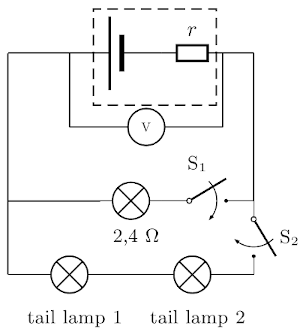
Worked example 10: Internal resistance and headlamps [NSC 2011 Paper 1]
The headlamp and two IDENTICAL tail lamps of a scooter are connected in parallel to a battery with unknown
internal resistance as shown in the simplified circuit diagram below. The headlamp has a resistance of
\(\text{2,4}\) \(\text{Ω}\) and is controlled by switch \(\textbf{S}_1\). The tail lamps are controlled
by switch \(\textbf{S}_2\). The resistance of the connecting wires may be ignored.
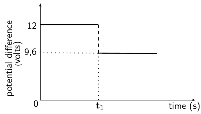
The graph alongside shows the potential difference across the terminals of the battery before and after
switch \(\textbf{S}_1\) is closed (whilst switch \(\textbf{S}_2\) is open). Switch \(\textbf{S}_1\) is
closed at time \(\textbf{t}_1\).
Use the graph to determine the emf of the battery.
(1 mark)
WITH ONLY SWITCH \(\textbf{S}_1\) CLOSED, calculate the following:
Current through the headlamp
(3 marks)
Internal resistance, \(r\), of the battery
(3 marks)
BOTH SWITCHES \(\textbf{S}_1\) AND \(\textbf{S}_2\) ARE NOW CLOSED. The battery delivers a current of
\(\text{6}\) \(\text{A}\) during this period.
Calculate the resistance of each tail lamp.
(5 marks)
How will the reading on the voltmeter be affected if the headlamp burns out? (Both switches
\(\textbf{S}_1\) and \(\textbf{S}_2\) are still closed.)
Write down only INCREASES, DECREASES or REMAINS THE SAME.