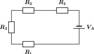
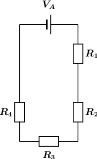
What type of circuit is shown in the diagram?
We need to determine whether the circuit is a series, parallel, or combination type of circuit. We do this by looking at how current flows through a circuit.
Recall that current is the movement of electric charge from a higher potential to a lower potential.
We assume that the flowing charge is positive (conventional current). This means that the charges start at the positive terminal of our power source (battery). Here the charges have lots of electrical potential energy.
The charges then move towards the negative terminal through the path that is created by the components and wires of the circuit. During this process, the electrical potential energy is converted into thermal energy by the resistors. Therefore, the charges have less electrical potential energy when they reach the negative terminal of the power source (battery).
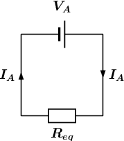
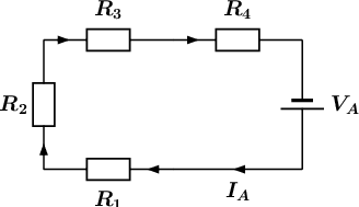
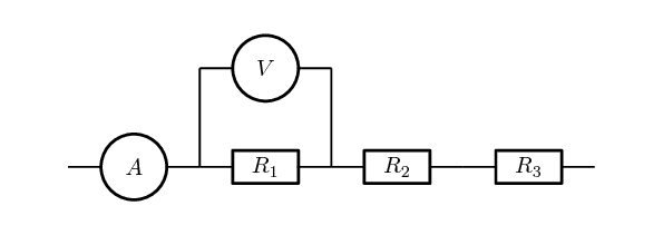
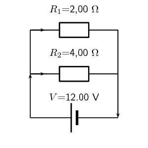
The flow of current is indicated by the arrows in the diagram below:
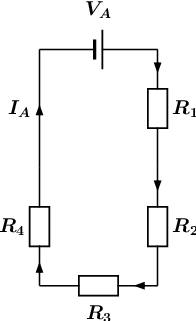
From the diagram it is clear that there is only one path for the current to flow, since the circuit does not split into two or more paths. This means that the current flows through all the components, one after the other (in series). We will label this current \(I_A\).
The circuit shown in the diagram is a series circuit.
\(0\)